Last Updated: November 14, 2021
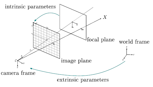
Camera calibration is an important first topic in 3D computer vision and also in image processing when removing distortion from an image taken with a pinhole camera. It is the process of determining the intrinsic and extrinsic parameters of the camera. \ The intrinsic parameters refer to the internal attributes about the camera - This is the focal length and its image center etc whilst its extrinsic parameters refer to the external attributes, which are the rotation and translation from a said origin point of the world which the camera is in.
The pin hole camera model is used to describe the process of how images are formed in cameras. Whilst the pin hole camera itself does not have lens, the model used in modern imaging accounts for the lens in modern cameras. \ The pin hole camera model can be represented by a matrix known as the camera projection matrix. It captures the process of how 3D points in the real world are transformed into 2D image points - Upcoming sections in this article will show that the matrix is composed of the intrinsic and extrinsic parameters of the digital camera.
The photo tourism project shows one of the many applications of 3D computer vision that can be achieved, especially when the intrinsic and extrinsic parameters of a camera are known. Other applications are measuring the size of a real world object, localizing the camera in a scene and estimating depth in a given image.
Intrinsic camera parameters ()
The intrinsic camera parameters are responsible for transforming points in the 3D world into the 2D image plane of the camera. There are 5 attributes used to encode information about the internal geometric attributes of the camera.
- The focal length (): This is the distance from the camera lens to the image plane (film) measured in pixels. They can also be viewed as scale factors as they translate 3D points into their corresponding 2D points in the x and y dimension.
- The Principal point offset (): is the straight line from the pinhole (camera lens' center) to the image plane. The ray of light from the pinhole is known as the principal ray and the point at which it hits the image plane is called the principal point or optical center of the camera.
- Axis skew : This is a deviation that could arise in digital cameras but i doubt this ever arises in analog cameras. The skew causes a shear distortion in the image projected unto the image plane.
The intrinsic camera parameters are usually fixed as they do not depend on the external world - except in the case of a varifocal lens where depends on the zoom. Therefore, can be calculated once for a camera and safely stored. \ The combined intrinsic parameters can be interpreted as a sequence of 2D affine transformations.
The final matrix is as a result of an axis skew (2D Shear), focal length as a 2D scaling operation and principal point offset to determine its position of the image plane.
The Absolute Conic
Without diving too deep into the maths as to why camera calibration works as this would be done in upcoming tutorials - there is the concept of the absolute conic. Consider a circle in the real world and a point that lies on that circle, then also consider an image of that circle taken with a camera - Projecting from the point in the image to the circle in the real world give us the concept of the absolute conic. The absolute conic has interesting properties which make it possible to retrieve the intrinsic parameters of the camera such as its invariance to rigid transformations like rotations. One way to look at this property is to imagine how the moon appears to follow you when driving at night on a straight road. \ For a more detailed introduction, please read the academic article by Zhengyou Zhang.
Extrinsic camera parameters
The extrinsic camera parameters help to determine the pose of the camera in the 3D world i.e the position of the camera and also its orientation at that position.
The extrinsic matrix is a 3D rigid transformation matrix consisting of a rotation and translation block.
Camera matrix
The camera matrix is a composition of the intrinsic and extrinsic parameters of the camera - The camera after all is simply mapping points in the 3D world to points in a 2D plane using a perspective transform. \ The camera matrix can be written as i.e where the extrinsic matrix maps the point into the camera world and the intrinsic matrix maps a point from its world into its 2D image plane - This is also referred to as the projection matrix.
Therefore, a point in the camera image is related to the point in the real world by the following equation
where and are both in the homogeneous form.
Camera Distortion
Distortion is a common visible artifact that occurs in pin-hole cameras due to the complexity involved in manufacturing camera lenses. The two most common form of distortion in cameras are radial and tangential distortion, there is also the complex or mustache distortion which is a combination of both radial and tangential distortion.


Radial Distortion
Radial distortion happens when light passing through the spherical lens of the camera is refracted as it hits the image plane. At the center of the lens, there is no refraction but as one progresses towards the edges, the rays begin to refract as it hits the image plane - A litmus test to show whether a camera has a radial distortion is to check for straight lines in the real world that appear curved in the image. The smaller the camera lens, the bigger the radial distortionTangential Distortion
This form of distortion happens when the image plane is not parallel to the lens, as a result, some parts of the image appear closer to the viewer.


A technique by Zhengyou Zhang, 1998 for correcting camera distortion can be modelled as
where is a model of the radial distortion and () are models of the tangential distortion and OpenCV has functions available that can solve for these parameters.
With the knowledge of the intrinsic, extrinsic and distortion parameters of the camera, we can represent them in code using the following data structures
struct intrinsic_t{
    cv::Mat cam_matrix = cv::Mat::eye(3,3,CV_64F); //3x3 floating point matrix
    cv::Mat distortion = cv::Mat::zeros(8,1,CV_64F);
};

struct extrinsic_t{
    cv::Mat rotation_matrix = cv::Mat::eye(3,3,CV_64F);
    cv::Mat translation_vec = cv::Mat::zeros(3,1,CV_64F);
};

struct camera_matrix_t{
    intrinsic_t intrinsic;
    extrinsic_t extrinsic;
};
Calibration Targets
Depending on the process being used to calibrate the camera, it is possible to classify the calibration target into 4 crude classification methods based on the calibration target, which are
- 3D reference patterns: Here the pattern's position and orientation in the 3D space are known and this is used to find correspondences in the 2D image captured - This method is very accurate.
- 2D planar patterns: A much more common pattern; Here, the planar pattern is shown in different positions and orientations, the only knowledge required are the dimension of the planar pattern which are easy to acquire. This is also the type of classification performed in this tutorial and this method produces very good estimates.
- 1D line patterns: These are patterns are usually in the form of the arrangement of physical objects and less paper patterns unlike the 3D & 2D patterns. An example is a string of tiny balls moved around a fixed point in space.
- self-calibration or 0D patterns: This method requires no patterns but simply extracts features from images taken by the camera in a static scene as it moves around. From the image information, there is already a constraint on the intrinsic parameters of the camera provided by the motion of the camera. This is also one of the key ideas in structure from motion where simple 3D reconstruction can be performed from multiple images of the scene.
The academic paper by Zhengyou Zhang provides an in-depth mathematical introduction, which explains the maths behind camera calibration while this tutorial focuses on the practical implementation of the techniques.
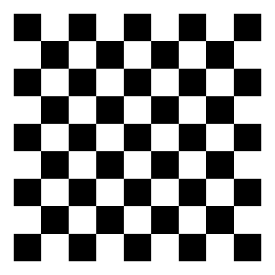
This calibration tutorial utilises 2D planar patterns as they are much easier to create and work quite well for most cameras. Regarding the pattern for the 2D surface, the following are patterns that could be used
- Chessboard: This is one of the most popular patterns used for camera calibration as the corners are easy to detect and are usually invariant to lens distortion - Although they are difficult to detect around the image borders.
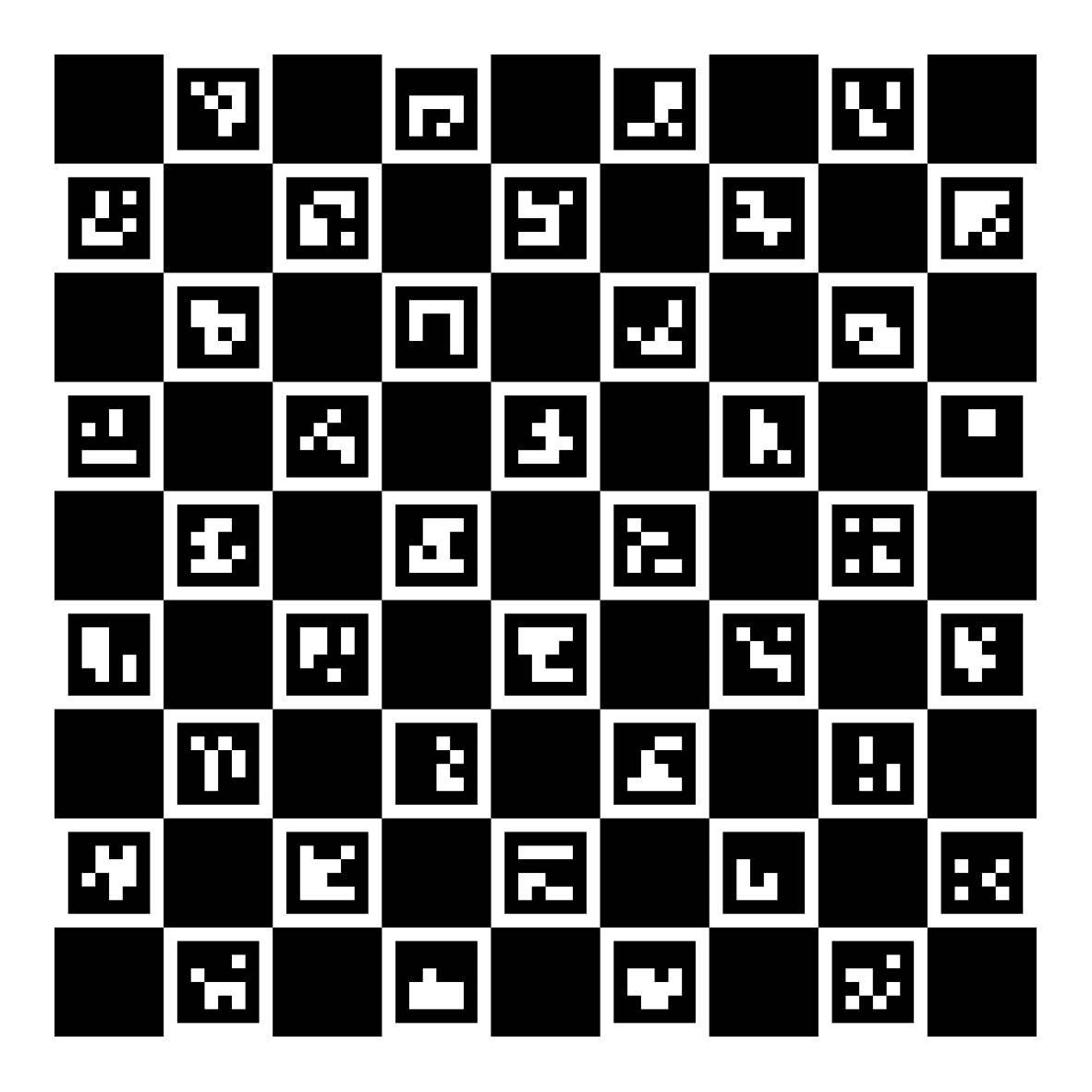
- ChArUco: ArUco markers are easy to detect but very hard to determine its corners. ChArUco combines the best of the chessboard and aruco patterns to leverage their advantages. They are ideal in situations where a high sub-pixel level accuracy is necessary
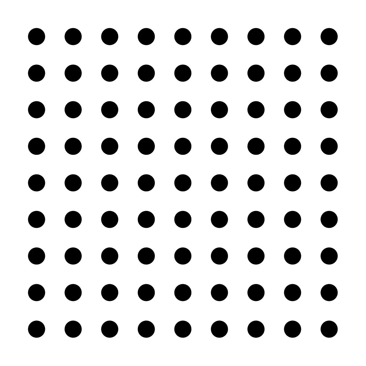
There other patterns like circles, but all the calibration targets mentioned provide constraints for the camera calibration algorithm, as they introduce assumptions that simplify the equations. For example, there is no depth in the targets as all the patterns lie on the same plane. Also, each point (corners) can be uniquely identified and they all lie in straight lines on the plane.

Several images of the calibration target needs to be taken in different orientations that vary significantly to ensure good estimates.
Camera Calibration Process
In the pin-hole camera model, the camera projection parameters estimate the relationship between pixels and real world points - An advantage to knowing this relationship is the ability to perform real world measurements. The goal of calibrating a camera is to estimate its intrinsic and distortion parameters (it is also possible to extract the extrinsic parameters of the camera).
To start, we need to have known 3D world coordinates and their corresponding 2D image points,we can use many of these correspondences to solve for the camera parameters (camera matrix and distortion coefficients)
The program we'd use to calibrate the camera using the OpenCV framework is as follows
#include <iostream>
#include <opencv2/opencv.hpp>
#include <vector>
#include <boost/filesystem.hpp>
#include <boost/range/iterator_range.hpp>
#include <string>
#include <yaml-cpp/yaml.h>

namespace fs = boost::filesystem;
using namespace std::placeholders;

int main(int argc, char *argv[]){
    //Parameters of the chessboard
    const cv::Size board_size(8,6);
    const float square_size = 15.0f;

    std::vector<cv::Mat> images;
    const std::string data_path = "./data/monocular";
    const auto iterator = fs::directory_iterator(data_path);

    for(const auto &entry: boost::make_iterator_range(iterator,{})){
        std::cout << "Reading image " << entry << std::endl;
        images.push_back( cv::imread(entry.path().string()) );
    }
The next portion of the code does the following
- Calibrates the camera
- Reprojects the image using the correct camera parameters
- Solves for the position and orientation of the camera for each image taken
camera_matrix_t camera_matrix = calibrate_camera(images, board_size, square_size);
std::cout << "Intrinsic matrix \n" << camera_matrix.intrinsic.cam_matrix << std::endl;
std::cout << "\nDistortion Coefficients \n" << camera_matrix.intrinsic.distortion << std::endl;
std::vector<cv::Mat> reproj_images(images.size());
auto func = std::bind(reproject_image, camera_matrix.intrinsic, _1);
std::transform(images.begin(), images.end(), reproj_images.begin(), func);
int counter = 0;
std::vector<float> mat_holder;
YAML::Emitter yaml_out;
yaml_out << "camera poses";
for(const auto &image: images){
cv::Mat combined_image;
cv::Mat reprojected_image = reproject_image(camera_matrix.intrinsic, image);
std::string calib_image_path = "./.tmp/calibrated_image_" + std::to_string(counter) + ".jpg";
std::string calib_image_joined_path = "./.tmp/calibrated_image_joined_" + std::to_string(counter) + ".jpg";
cv::hconcat(image, reprojected_image, combined_image);
cv::imwrite(calib_image_path, reprojected_image);
cv::imwrite(calib_image_joined_path, combined_image);
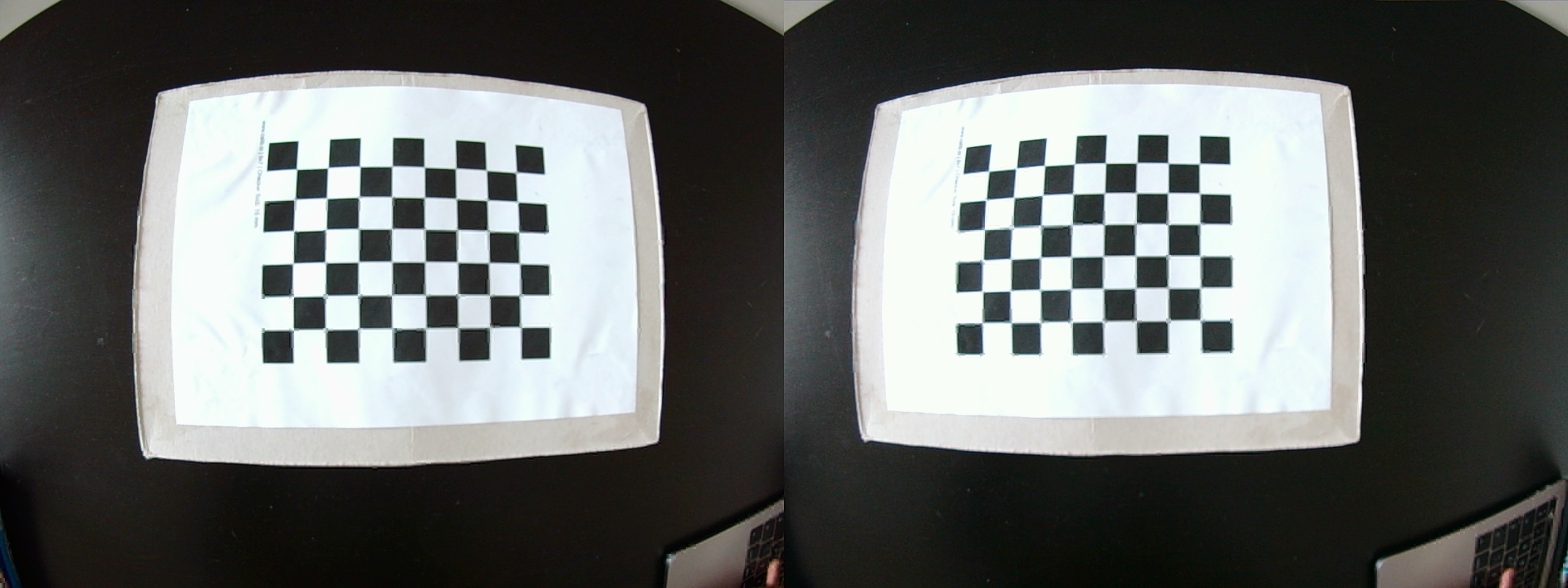
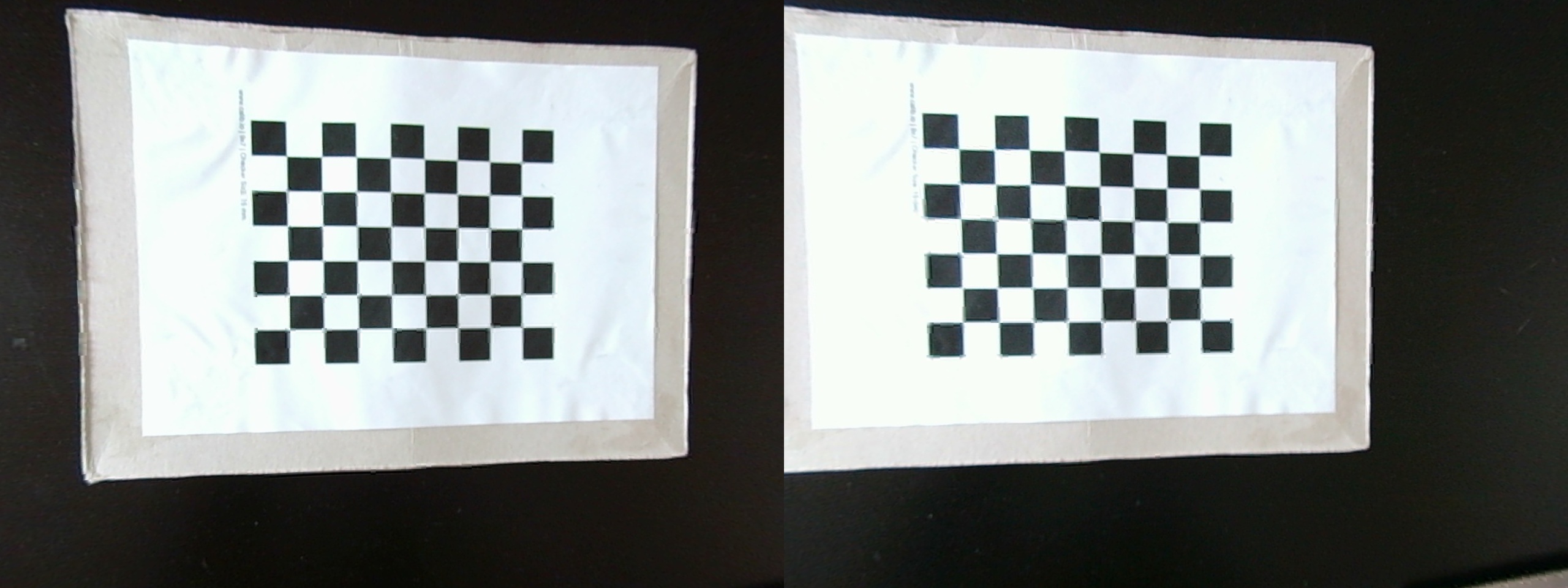
cv::imshow("Distorted (L) and Undistorted (R) image", combined_image);
cv::waitKey(100);
extrinsic_t pose = get_camera_chessboard_pose(board_size, square_size, camera_matrix.intrinsic, image);
Lastly, we then log the data we have collected to a file for later use. In this tutorial, I created a separate program using regl and worldview where i plot the camera poses with respect to the chessboard pattern
        yaml_out << YAML::BeginMap;
        yaml_out << YAML::Key << "img_name";
        yaml_out << YAML::Value << calib_image_path;
        yaml_out << YAML::Key << "rotation";

        pose.rotation_matrix.col(0).copyTo(mat_holder);
        yaml_out << YAML::Value << YAML::BeginSeq << mat_holder << YAML::EndSeq;
        yaml_out << YAML::Key << "translation";
        pose.translation_vec.col(0).copyTo(mat_holder);
        yaml_out << YAML::Value << YAML::BeginSeq << mat_holder << YAML::EndSeq;
        yaml_out << YAML::EndMap;

        counter++;
    }

    std::ofstream fout(".tmp/file.yaml");
    fout << yaml_out.c_str();
}
Print a pattern and attach it to a planar surface
For this tutorial, i'd be using a 2D planar pattern attached to a flat surface. Calib.io has a good pattern generator and OpenCV also has functions for drawing patterns either manually or using some built in ones such as the ChAruco pattern creator.
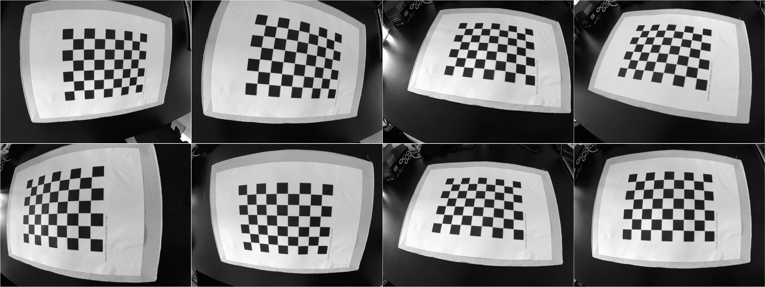
Capture many images of the pattern
Take a few images of the model plane under different orientations by moving either the plane or the camera; Later in this tutorial, there is a section where I list some factors to consider when taking these calibration images.
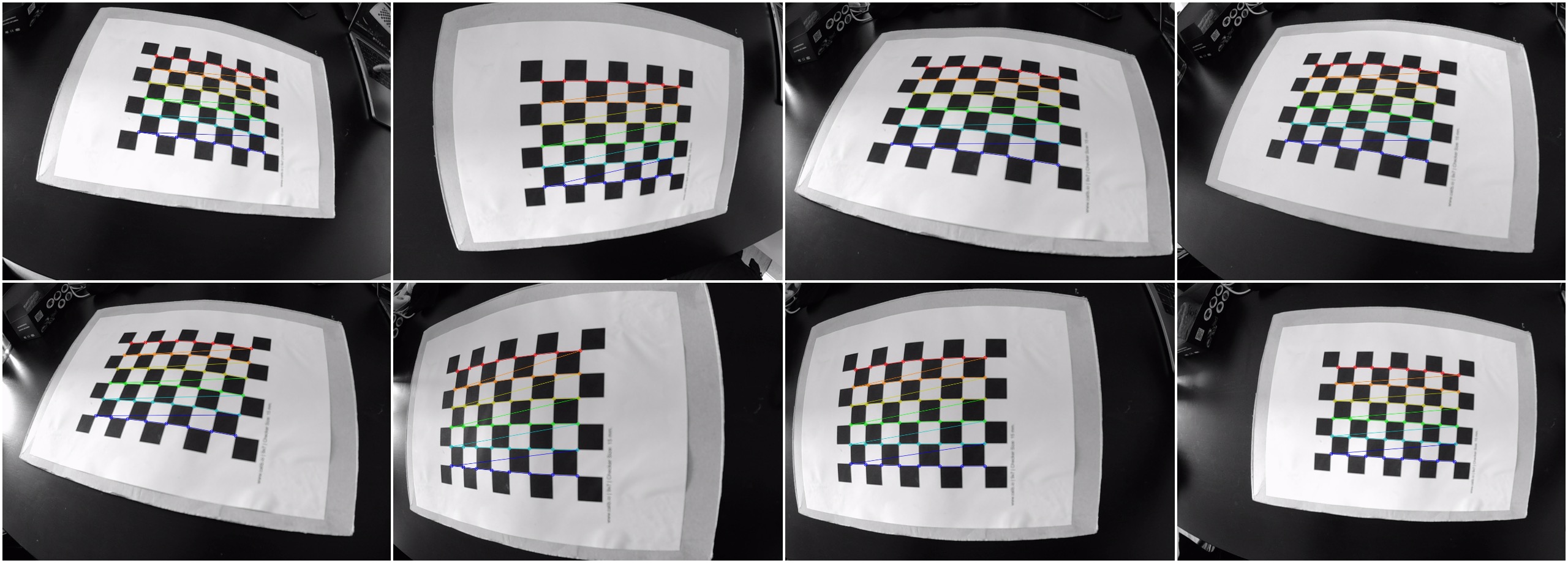
Detect the chessboard corners in the images
The next task is to detect the feature points in the images; Many of the functions that would be shown onwards are the implementations of the functions used earlier in the main program.
using detected_corners_t = std::tuple<
                std::vector<std::vector<cv::Point3f>>, //world corners
                std::vector<std::vector<cv::Point2f>> //detected corners
            >;

//detects chessboard corners in the given images
detected_corners_t detect_corners(std::vector<cv::Mat> images, cv::Size board_size, float square_size){
    std::vector<std::vector<cv::Point2f>> detected_corners;
    std::vector<std::vector<cv::Point3f>> corners;
    int flags = cv::CALIB_CB_ADAPTIVE_THRESH | cv::CALIB_CB_NORMALIZE_IMAGE;
    cv::TermCriteria term_criteria( cv::TermCriteria::EPS + cv::TermCriteria::COUNT, 30, 0.1);
    cv::Size image_size = images.front().size();

    for(auto const& image: images){
        std::vector<cv::Point2f> c_corners;
        cv::Mat img_clone = image.clone();
        cv::Mat gray_image;
        bool c_found = cv::findChessboardCorners(image, board_size, c_corners, flags);
        cv::cvtColor(image, gray_image, cv::COLOR_BGR2GRAY);
        cv::cornerSubPix(gray_image, c_corners, cv::Size(11,11), cv::Size(-1,-1), term_criteria);
        cv::drawChessboardCorners(img_clone, board_size, cv::Mat(c_corners), c_found);

        detected_corners.push_back( c_corners );
        corners.push_back( calculate_target_corners(board_size, square_size) );
    }

    return std::make_tuple(corners, detected_corners);
}
Estimate the camera parameters
To estimate the camera parameters, we would need to perform the following steps
- Estimate the five intrinsic parameters and all the extrinsic parameters
- Estimate the coefficients of the radial distortion
- Refine all parameters, including lens distortion parameters by an iterative minimisation process.
Luckily OpenCV has functions that we can use to performed the aforementioned in a single function call as shown below
camera_matrix_t calibrate_camera(std::vector<cv::Mat> images, cv::Size board_size, float square_size){
    camera_matrix_t cam_mtx;
    detected_corners_t l_detected_corners = detect_corners( images, board_size, square_size );
    std::vector<std::vector<cv::Point3f>> pattern_corners = std::get<0>(l_detected_corners);
    std::vector<std::vector<cv::Point2f>> detected_corners = std::get<1>(l_detected_corners);
    cv::Size image_size = images.front().size();
    std::vector<cv::Mat> board_rotations;
    std::vector<cv::Mat> board_translations;

    double error = cv::calibrateCamera(pattern_corners, detected_corners, image_size,
                                    cam_mtx.intrinsic.cam_matrix, cam_mtx.intrinsic.distortion,
                                    board_rotations, board_translations);
    std::cout << "Root-Mean-Square re-projection error = " << error << std::endl;
    return cam_mtx;
}
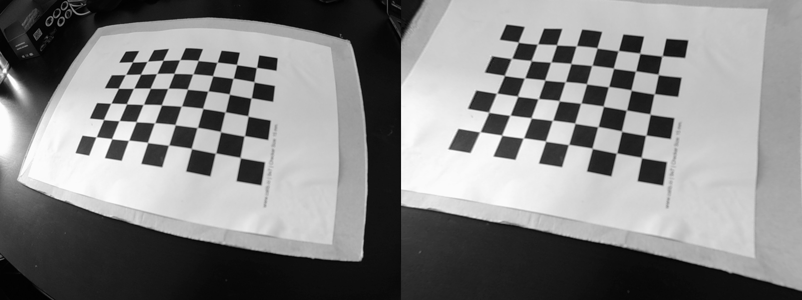
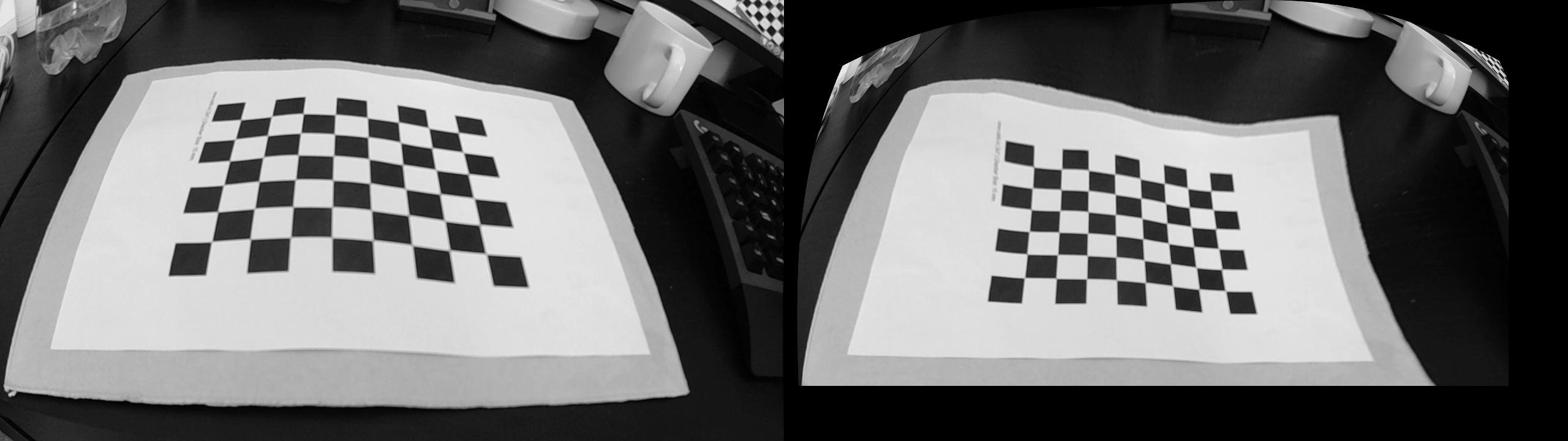
Reproject the image
In the process of undistorting, the image will be warped, cropped and resized - This might given a sense of zooming in.
cv::Mat reproject_image(intrinsic_t intrinsic, cv::Mat image){
    cv::Mat result;
    cv::undistort(image, result, intrinsic.cam_matrix, intrinsic.distortion);
    return result;
}
Tips for camera calibration
Good calibration result should have values between 0 and 1, higher numbers usually indicate some error in the calibration process. The following are some tips on how to capture the images to ensure good calibration results:
- Hold the calibration pattern horizontally, if using a checkerboard or similar pattern, to allow for more sample points
- Capture numerous images in different poses - combining some of the following also helps improve calibration results
- X axis calibration: Make sure the pattern is at the left and right edges in the camera's field of view
- Y axis calibration: Make sure to capture images of the pattern in different positions along the top and bottom edges in the field of view
- Skew calibration: While in the center of view, adjust the pose of the pattern such that it is tilting at different angles.
- There is no formula for determining the maximum number of images to use, the more images available, the better the result. For my experiments, I used around 47 images. But from a mathematical perspective, the minimum number of images required is 3 and each image has to have at least 4 points (corners) detected.
Stereo Camera Calibration
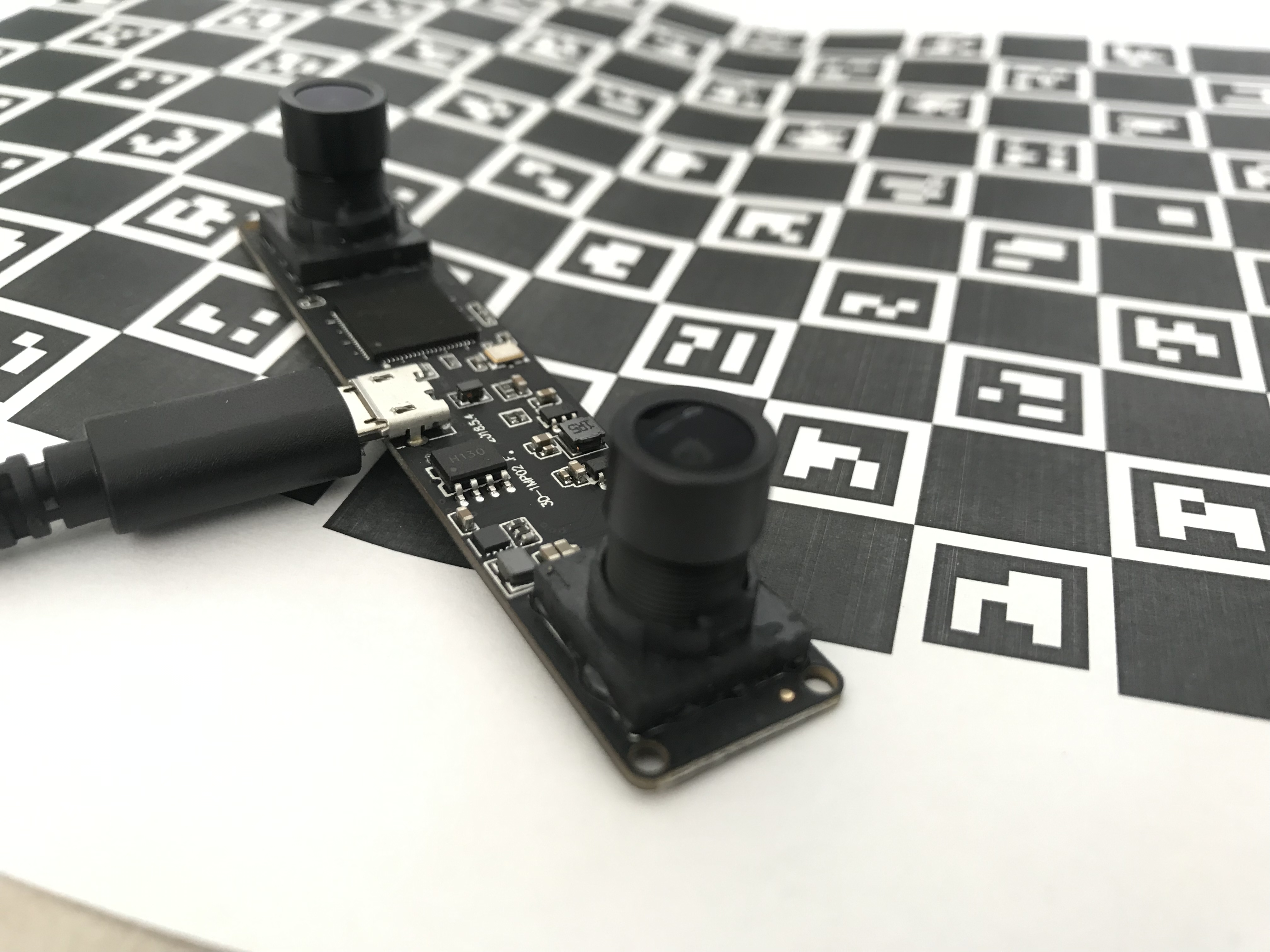
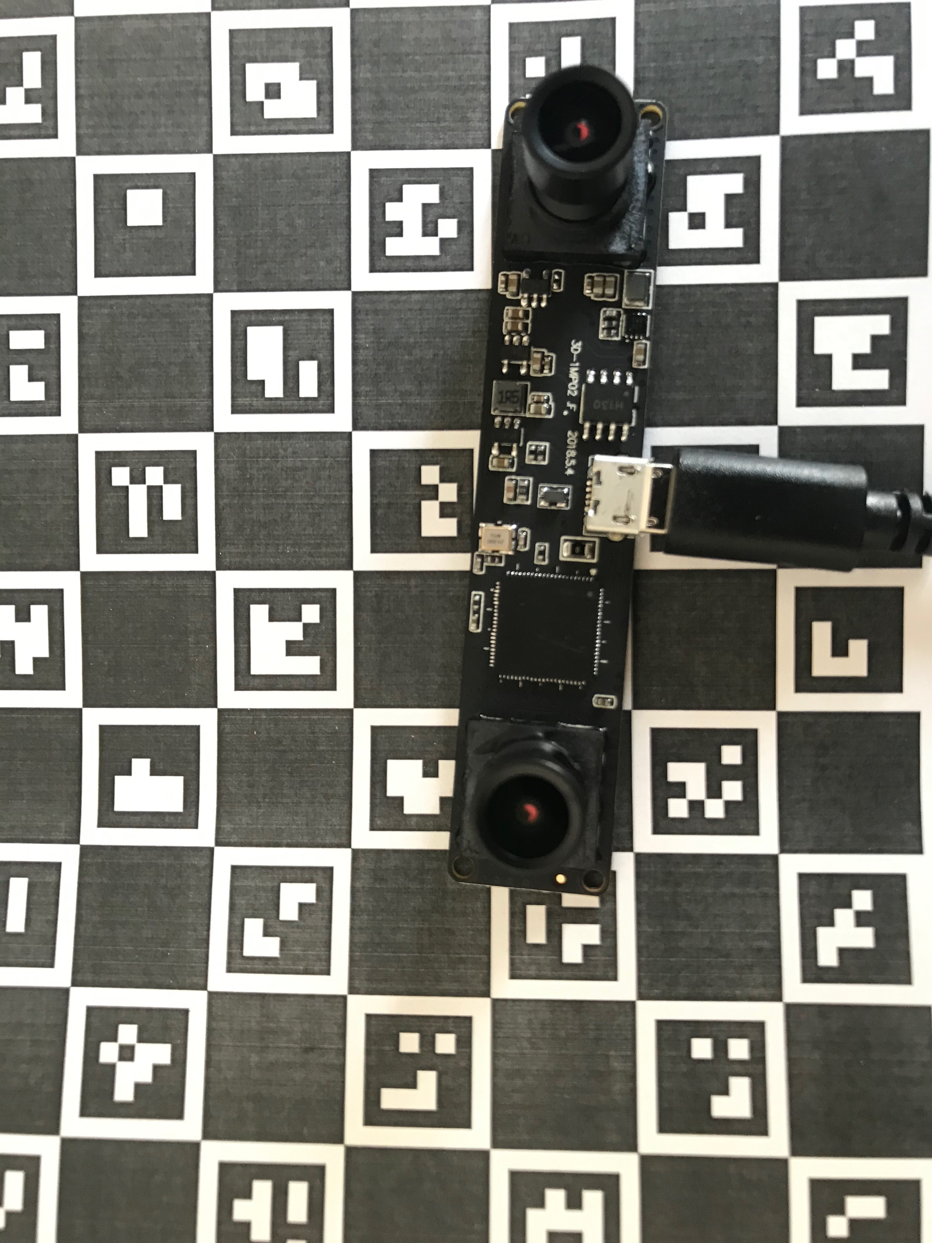
Building on what has been done, in the case of stereo calibration, we now need to extract some more parameters to gain a full picture of the camera system
- Rotation of detected points between both cameras
- Translation of detected points between both cameras
const std::string data_path = "./data/stereo";
const auto iterator = fs::directory_iterator(data_path);
std::cout << "Stereo calibration " << std::endl;
std::vector<std::tuple<cv::Mat,cv::Mat>> stereo_images;
for(const auto &entry: boost::make_iterator_range(iterator,{})){
cv::Mat image = cv::imread(entry.path().string());
std::cout << "Reading image " << entry << " with size = " << image.size() << std::endl;
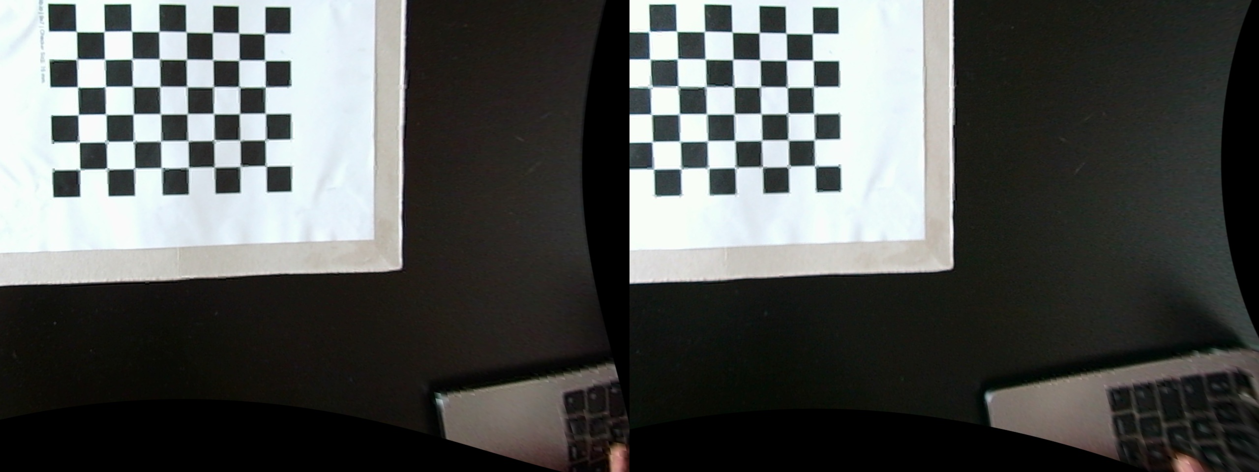
cv::Mat left_image = image(cv::Rect(0, 0, image.cols/2, image.rows));
cv::Mat right_image = image(cv::Rect(image.cols/2, 0, image.cols/2, image.rows));
stereo_images.push_back( std::make_tuple(left_image, right_image));
}
stereo_t stereo_data = calibrate_stereo_camera(stereo_images, board_size, square_size);
for(const auto &stereo_pair: stereo_images){
cv::Mat l_undistort = reproject_image( stereo_data.left.intrinsic, std::get<0>(stereo_pair) );
cv::Mat r_undistort = reproject_image( stereo_data.right.intrinsic, std::get<1>(stereo_pair) );
auto rectified_stereo_pair = stereo_rectify( stereo_pair, stereo_data );
}
The data structure used to hold the stereo camera parameters
struct stereo_t {
    camera_matrix_t left;
    camera_matrix_t right;
    cv::Mat left_right_rotation = cv::Mat::eye(3,3,CV_64F);
    cv::Mat left_right_translation = cv::Mat::zeros(3,1,CV_64F);
    cv::Mat fundamental = cv::Mat::eye(3,3,CV_64F);
    cv::Mat essential = cv::Mat::eye(3,3,CV_64F);
    cv::Mat left_rectification = cv::Mat::eye(3,3,CV_64F);
    cv::Mat right_rectification = cv::Mat::eye(3,3,CV_64F);
    cv::Mat left_projection = cv::Mat::zeros(3,4,CV_64F);
    cv::Mat right_projection = cv::Mat::zeros(3,4,CV_64F);
    cv::Mat disparity_depth = cv::Mat::zeros(4,4,CV_64F);
};
Due to the high dimensionality of the parameter space and noise in the input data, the function can diverge from the correct solution. Therefore, it is important that you provide OpenCV with initial estimates of what the intrinsic parameters are for each camera else the re-projection errors would be high. This is done in the following code, where we first calibrate the cameras individually to obtain the estimates before solving again for all the parameters.
stereo_t calibrate_stereo_camera(std::vector<std::tuple<cv::Mat,cv::Mat>> stereo_pairs, cv::Size board_size, float square_size){
    stereo_t stereo_data;
    std::vector<cv::Mat> left_images;
    std::vector<cv::Mat> right_images;

    int flags = cv::CALIB_FIX_INTRINSIC;

    for(auto const& stereo_pair: stereo_pairs){
        left_images.push_back( std::get<0>(stereo_pair) );
        right_images.push_back( std::get<1>(stereo_pair) );
    }
    cv::Size image_size = left_images.front().size();
    cv::Mat stereo_pair_errors;

    //Optimisation step, solve for initial estimates of the intrinsic parameters
    stereo_data.left = calibrate_camera( left_images, board_size, square_size );
    stereo_data.right = calibrate_camera( right_images, board_size, square_size );

    detected_corners_t l_detected_corners = detect_corners( left_images, board_size, square_size );
    detected_corners_t r_detected_corners = detect_corners( right_images, board_size, square_size );
    std::vector<std::vector<cv::Point3f>> pattern_corners = std::get<0>(l_detected_corners);

    double final_error = cv::stereoCalibrate( pattern_corners,
                            std::get<1>(l_detected_corners), std::get<1>(r_detected_corners),
                            //refine the estimates of the intrinsic parameters of both the left and right
                            stereo_data.left.intrinsic.cam_matrix,
                            stereo_data.left.intrinsic.distortion, stereo_data.right.intrinsic.cam_matrix,
                            stereo_data.right.intrinsic.distortion,
                            image_size, stereo_data.left_right_rotation,
                            stereo_data.left_right_translation, stereo_data.essential,
                            stereo_data.fundamental, stereo_pair_errors, flags
                    );
    std::cout << "Final re-projection error value = " << final_error << std::endl;

    return stereo_data;
}
Lastly, having calibrated the stereo camera, we can then use those parameters to correctly rectify images taken, the code shown below as
std::tuple<cv::Mat,cv::Mat> stereo_rectify(std::tuple<cv::Mat,cv::Mat> stereo_pair, stereo_t stereo_params, bool cropped){
    cv::Mat left_map_x, left_map_y, right_map_x, right_map_y;
    cv::Mat undistort_left, undistort_right;
    cv::Rect left_roi, right_roi;
    int flags = cv::CALIB_ZERO_DISPARITY;

    cv::stereoRectify(
                stereo_params.left.intrinsic.cam_matrix, stereo_params.left.intrinsic.distortion,
                stereo_params.right.intrinsic.cam_matrix, stereo_params.right.intrinsic.distortion,
                std::get<0>(stereo_pair).size(),
                stereo_params.left_right_rotation, stereo_params.left_right_translation,
                stereo_params.left_rectification, stereo_params.right_rectification,
                stereo_params.left_projection, stereo_params.right_projection,
                stereo_params.disparity_depth,
                flags, -1, cv::Size(0,0), &left_roi, &right_roi
    );
    cv::initUndistortRectifyMap(
                stereo_params.left.intrinsic.cam_matrix, stereo_params.left.intrinsic.distortion,
                stereo_params.left_rectification, stereo_params.left_projection, std::get<0>(stereo_pair).size(),
                CV_32F, left_map_x, left_map_y
    );
    cv::initUndistortRectifyMap(
                stereo_params.right.intrinsic.cam_matrix, stereo_params.right.intrinsic.distortion,
                stereo_params.right_rectification, stereo_params.right_projection, std::get<1>(stereo_pair).size(),
                CV_32F, right_map_x, right_map_y
    );

    cv::remap(std::get<0>(stereo_pair), undistort_left, left_map_x, left_map_y, cv::INTER_LINEAR );
    cv::remap(std::get<1>(stereo_pair), undistort_right, right_map_x, right_map_y, cv::INTER_LINEAR );

    if( cropped ){
        undistort_left = undistort_left(left_roi);
        undistort_right = undistort_right(right_roi);
    }

    return std::make_tuple(undistort_left, undistort_right);
}
Camera Pose Visualisation
Given the 3D points of an object (chessboard pattern) and its corresponding 2D points (detected corners), we can use the solvePnP function in OpenCV to determine the pose of the camera during the image capture process. This is usually known as Perspective-N-Points and later tutorials would show the Augmented Reality applications where we can render an artificially generated object into a scene while moving the camera around.
extrinsic_t get_camera_chessboard_pose(cv::Size board_size, float square_size, intrinsic_t camera_matrix, cv::Mat image, rotation_format format){
    extrinsic_t pose;
    std::vector<cv::Point3f> board_points = calculate_target_corners(board_size, square_size);
    std::vector<cv::Point2f> chess_corners;
    int flags = cv::CALIB_CB_ADAPTIVE_THRESH | cv::CALIB_CB_NORMALIZE_IMAGE;
    bool c_found = cv::findChessboardCorners(image, board_size, chess_corners, flags);
    if( !c_found )
        std::cout << "FAILED TO FIND CHESSBOARD CORNERS" << std::endl;
    else{
        cv::Mat rotation = cv::Mat::zeros(3,1,CV_64F);
        cv::solvePnP(board_points, chess_corners, camera_matrix.cam_matrix,
                    camera_matrix.distortion, rotation,
                    pose.translation_vec, false
        );
        if( format == rotation_format::rotation_matrix)
            cv::Rodrigues(rotation, pose.rotation_matrix);
        else
            pose.rotation_matrix = rotation;
    }
    return pose;
}
To make the presentation clearer, only 3 camera poses are shown below. The visualisation was written in a separate application using WebGL (Worldview and regl) - The purple cones represent the camera poses while the white rectangular board represents the chessboard.
References
- Pinhole camera model
- Pattern generator for calibration
- A Flexible New Technique for Camera Calibration
- Interactive application showing the effects of different camera attributes
- ROS Tutorial on Camera Calibration and ROS module for camera calibration
- A Flexible New Technique for Camera Calibration by Zhengyou Zhang, 1998 and Academic book chapter
- http://www.cs.ait.ac.th/~mdailey/papers/Bukhari-RadialDistortion.pdf
- Multiple View Geometry